..-+-' Hapsira Tirona '-+-.. - on CyberSpace

..-+-' Hapsira Tirona '-+-.. - on Embedded


Embedded
HOMbEddd
Rreth Nesh
Contact us
Galeria Fotografike

Embedded user?!

Hello everyone, 

I'm going to publish here some of the work done on MEMS accelerometer from Analog Device ADXL312, Arduino UNO Board and ADuC7020 MCU.

While writing my thesis focused on describing the movement of a rigid body in 3D, I had to work on an embedded system composed of MEMS sensors, BT radio communication and a MCU.

Firstly I'll put here some documentation and some test code. The project is under development so I'll post here new things as soon as I can.

If you want to contact me scroll down to leave a comment, or send an e-mail at: infotirona [at] yahoo [dot] com

Thank you!


________________________________________________

ADXL312 Soldering Scheme


Soldering by hand an ADXL312 isn't the simplest thing to do. My fist test was made on a hand soldered ADXL312. The scheme was simple. I didn't connect the interrupt pins, just the minimum of connections needed for a 4-Ways SPI(SDI-MOSI, SDO-MISO, SCLK, CS).


Scheme


Breakout


____________________________________________________

ADXL312 to ArduinoUNO Hookup


The soldered by hand ADXL312 was connected to the ArduinoUNO. The fist test was made by setting up the SPI protocol on Arduino(CPOL=1 and CPHA=1, aka MODE3; MSB first) and reading the register 0x00 on the ADXL312. This register contains the accelerometer's ID (0xE5) and it is a read-only register.

Sending a 0x80 byte of data over SPI asks the ADXL312 to read the 0x00 register. ADXL312 responds to this command sending, on the 8 clock signals that follows, the content of the register(0xE5).


Hookup


#include "SPI.h"

const static byte ID = 0x80;             // READ ID

const static uint8_t CS = 9;             // CHIP SELECT

void setup()
{
  pinMode(CS, OUTPUT);
  digitalWrite(CS, HIGH);

  SPI.begin(); // SCLK 13, MISO 12, MOSI 11, CS 10
  SPI.setDataMode(SPI_MODE3); // CPOL=1 & CPHA=1
  SPI.setBitOrder(MSBFIRST); 
  SPI.setClockDivider(SPI_CLOCK_DIV128);

  Serial.begin(115200); 
  Serial.println("/------------------------------------------------------------+");
  Serial.println("|                                                            |");
  Serial.println("|                        SYSTEM READY!                       |");
  Serial.println("|                                                            |");
  Serial.println("+------------------------------------------------------------/");
  Serial.println();
  

void loop() 
{
  Serial.println(spiRead(ID));
}

byte spiRead (byte a) 
  byte out;

  digitalWrite(CS, LOW);
  SPI.transfer(a);
  out = SPI.transfer(0x8E);
  digitalWrite(CS, HIGH);

  return out;  
}


____________________________________________________

ADXL312 to ADuC7020 Miniboard Hookup


I've connected the ADXL312 to the ADuC Miniboard. The fist test was made as in the Arduino post, by setting up the SPI protocol on the ADuC7020(CPOL=1 and CPHA=1; MSB first; Continuous transfer; TX and IRQ) and reading the register 0x00 on the ADXL312. As I said before, this register contains the accelerometer's ID (0xE5) and it is a read-only register.

Sending a 0x80 byte of data over SPI asks the ADXL312 to read the 0x00 register. ADXL312 responds to this command sending, on the 8 clock signals that follows, the content of the register(0xE5).


ADuC_Hookup


#include <ADuC7020.h>

// Transmit one byte and read answer
unsigned char SPIRead(unsigned char a);

int main(void)
{
  POWKEY1 = 0x01;
  POWCON = 0x00;
  POWKEY2 = 0xF4;

  GP1DAT = 0xD0000000; // MOSI, SCLK and CS as output
  GP1CON = 0x02220000; // Pins as SPI port
  SPICON = 0x164F; // Master mode, phase 1, polarity 1, TX and IRQ, MSB first, Enable SPI

  // Set divider for SPI   fs = fc / 2 (1 + div)  || div = (fc / 2 fs) - 1
  SPIDIV = 0x05;

  // Variables
  unsigned char ch = 0;
  GP1DAT |= 0x00800000; // Set CS high

  // Loop forever
  while(1) 
  {
    GP1DAT &= ~0x00800000; // Set CS low
    ch = SPIRead(0x80);
    GP1DAT |= 0x00800000; // Set CS high
  }
}

// Transmit one byte via SPI and read answer
unsigned char SPIRead(unsigned char a) {

  unsigned char data = 0;

  // Send the data
  SPITX = a;
  // Wait for the transfer to complete
  while(!(SPISTA&0x08));
  data = SPIRX;

  SPITX = 0x8E;
  // Wait for the transfer to complete
  while(!(SPISTA&0x08));  
  // Get the data received
  data = SPIRX;

  return data;
}


____________________________________________________

ADXL312 to TI Lauchpad Hookup


The soldered by hand ADXL312 was connected to the Texas Instruments LaunchPad. The fist test was made by setting up the SPI protocol on the Launchpad(CPOL=1 and CPHA=1; MSB first) and reading the register 0x00 on the ADXL312. This register contains the accelerometer's ID (0xE5).

Sending a 0x80 byte of data over SPI asks the ADXL312 to read the 0x00 register. ADXL312 responds to this command sending, on the 8 clock signals that follows, the content of the register(0xE5).


ADuC_Hookup


#include <msp430g2231.h>

void main(void)
{

volatile unsigned int i;
WDTCTL = WDTPW + WDTHOLD; // Stop watchdog timer
P1OUT = 0x10; // P1.4 set, else reset
P1REN |= 0x10; // P1.4 pullup
P1DIR = 0x04; // P1.3 output, else input

USICTL0 |= USIPE7 + USIPE6 + USIPE5 + USIMST + USIOE; // Port, SPI master
USICTL1 |= USICKPH + USIIE; // Counter interrupt, flag remains set
USICKCTL = USIDIV_4 + USISSEL_2 + USICKPL; // /16 SMCLK
USICTL0 &= ~USISWRST; // USI released for operation
USICNT |= USI16B;

__delay_cycles(500);

P1DIR &= ~0x04;
USISRH = 0x80; // FIRST Byte
USISRL = 0x8E; // SECOND Byte
USICNT |= 16; // init-load counter
P1DIR |= 0x04;
_BIS_SR(LPM0_bits + GIE); // Enter LPM0 w/ interrupt
}

// USI interrupt service routine
#pragma vector=USI_VECTOR
__interrupt void universal_serial_interface(void)
{
P1DIR &= ~0x04;
USISRH = 0x80;
USISRL = 0x8E;
USICNT |= 16; // re-load counter
P1DIR |= 0x04;
}


____________________________________________________

Hacking ArduinoUno - 2xFaster SPI when using ADXL312 accelerometer


I've completed the first tests on ADXL312 and ArduinoUno. The sensor seems great, it has a very good resolution and sensitivity. It is also fast, maybe too much to be used with an ATMEGA328. But this was just my first impression. I've analyzed the signal on a Level Logic Analyzer and I found that there was a long delay(2xSCLK) on the assertion and deassertion of the CS pin.

Due to the good generalization of the digitalWrite() function, there is a big overhead each time you want to RX/TX data via SPI. The digitalWrite() function has to call other functions that searches the mapped pin and returns the value to the function. Calling functions and searching values takes time and when you work at 4MHz it costs a lot of time considering that this is a redundant work.

The simplest way to avoid the overhead(at high level) is to check the values returned by the function called after a digitalWrite(); and save them in the sketch.

I've also modified the SPI.h and SPI.cpp files to use them with ADXL312. If you want to use them don't delete the old ones in the ArduinoUno IDE!


#include "SPI.h"
#include "wiring_private.h"
#include "pins_arduino.h"

#define SERIAL 1
#define SAMPLE 1

// const static float G = 9.80505; // Gravity's acceleration in Milan
// const static float MG = 0.00980505; // G/1000
// const static float SENS = 2.9; // mG/LSB from ADXL312 Datasheet

const static byte ID = 0x80; // READ ID
const static byte BW = 0xAC; // READ BW
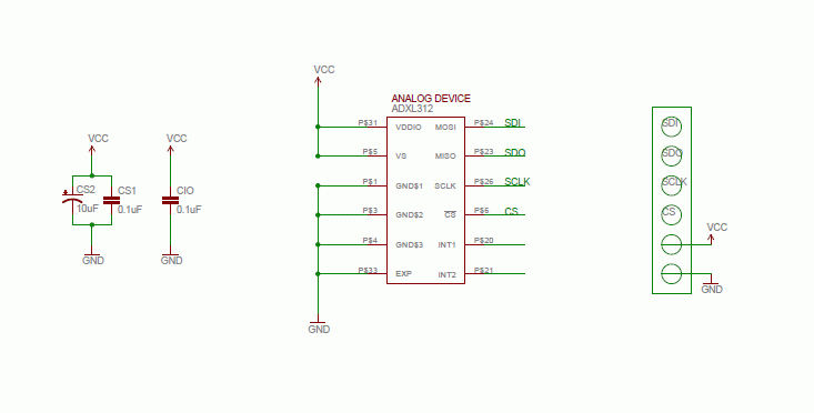
const static uint8_t CS = 9; // Chip Selet connected at PIN9
const static float SPMG = 0.028434645; // sens*mG

byte data[6]; // Array where to save DATA registers content
uint16_t value; // Store DATA_1 & DATA_0 values for X, Y and Z
byte out;

/* digitalWrite()'s overhead avoidance */
uint8_t CSport;
uint8_t CSbit;
volatile uint8_t *CSreg;

void setup()
{
  CSport = digitalPinToPort(CS);
  CSbit = digitalPinToBitMask(CS);
  CSreg = portOutputRegister(CSport);

  delay(1000);

  pinMode(CS, OUTPUT); // Set Chip Selet pin as output
  digitalWrite(CS, HIGH); // Chip Select HIGH, no comunication
  // SCLK 13, MISO 12, MOSI 11, CS 10, MASTER, CPOL_1, CPHA_1, MSB, 4MHz, NO INT
  SPI.begin();

#if SAMPLE

  spiWrite(0x31, 0x0B); // Set DATA_FORMAT as RIGHT_JUSTIFIED
  spiWrite(0x2D, 0x08); // Set POWER_CTL in FULL_RES at +/-12g
  spiWrite(0x2E, 0x80); // Set INT_ENABLE at DATA_READY
#endif

#if SERIAL

  Serial.begin(115200); // Start serial comunication at 115200 bps
  Serial.println("/------------------------------------------------------------+");
  Serial.println("|                                                           |");
  Serial.println("|                       SYSTEM READY!                        |");
  Serial.println("|                                                           |");
  Serial.println("+------------------------------------------------------------/");
  Serial.println();
#endif

}

void loop()
{

  spiRead(ID, &out);

#if SERIAL

  Serial.println(out, HEX);
#endif

#if SAMPLE

  int j = 0; // For Serial.print purpouse

  float out = 0; // Store x^2 + y^2 + z^2 value
  float comp = 0; // Store the positive complement value of acceleration

  spiReadMore(0xF2, data);

  for(int i = 5; i >= 0; i = i - 2){
   value = 0;
   value = ((data[i] << 8) | data[i-1]);

   comp = complement(value); // Calculate g value
   out += (comp*comp); // Calculare z^2 + y^2 + z^2

   Serial.write(90 - j); // Axis
   Serial.print(": ");
   printData(value); // Print Two's complement value
   Serial.print(" >> ");

   j++;
  }

  Serial.print("g: ");
  Serial.print(sqrt(out)); // Calculate g vector value and print it on Serial terminal
  Serial.println();


  // delayMicroseconds(1);

  delay(200);
#endif

}

// Prints the parameters value in Two's complement
void printData(uint16_t data)
{
  uint16_t temp;

  if (data & 0xF000) // If negative
  {
   temp = ((data ^ 0xFFFF) + 1) * (-1); // Calculate complement
   Serial.print((temp * SPMG), DEC); // Calculate acceleration value
  }
  else // If positive
  {
   Serial.print(PSTR(" "));
   Serial.print(((data) * SPMG), DEC); // Calculate acceleration value
  }
}

// Returns the positive Two's complement of the parameter
float complement(uint16_t data)
{
  float temp; // Store the calculated output value

  if (data & 0xF000) // If negative
  {
   temp = SPMG * ((data ^ 0xFFFF) + 1) * (-1); // Calculate two's complement and acceleration
  }
  else // If positive
  {
   temp = SPMG * data; // Caculate acceleration value
  }

  return temp;
}

// TX two bytes of data. Writes data d in register a via SPI
void spiWrite (byte a, byte d)
{
  WriteCS(LOW, CSbit, CSreg);
  SPI.write(a, d);
  WriteCS(HIGH, CSbit, CSreg);
}

// TX and RX one byte on data via SPI and return RXed
void spiRead (byte a, byte *data)
{
  WriteCS(LOW, CSbit, CSreg);
  SPI.transfer(a, data);
  WriteCS(HIGH, CSbit, CSreg);
}

// TX one byte and RX 6 bytes of data via SPI, starting from register a
// Store received bytes in data array
void spiReadMore (byte a, byte *data)
{
  WriteCS(LOW, CSbit, CSreg);
  SPI.readmore(a, data);
  WriteCS(HIGH, CSbit, CSreg);
}

void WriteCS(uint8_t CSval, uint8_t CSbit, volatile uint8_t *CSreg)
{
  if (CSval == LOW) {
   *CSreg &= ~CSbit;
  } else {
   *CSreg |= CSbit;
  }
}


/* Modified SPIClass in SPI.h */
class SPIClass {
public:
  inline static void transfer(byte a, byte *_data);
  inline static void write(byte _data1, byte _data2);
  inline static void readmore(byte _data1, byte *_data2);

  // SPI Configuration methods
  inline static void attachInterrupt();
  inline static void detachInterrupt(); // Default

  static void begin(); // Default
  static void end();

  static void setBitOrder(uint8_t);
  static void setDataMode(uint8_t);
  static void setClockDivider(uint8_t);
};


/* Modified void SPIClass::transfer(byte a, byte *_data) in SPI.h */
// TX 2 bytes and RX 1 byte
void SPIClass::transfer(byte a, byte *_data)
{
  SPDR = a;
  while ( !( SPSR & 0x80 ) );
  *_data = SPSR; // Clear RX flag
  *_data = SPDR; // Dummy read RXed data

  SPDR = 0x8E;
  while ( !( SPSR & 0x80 ) );
  *_data = SPSR; // Clear flag
  *_data = SPDR; // Read RXed data
}


/* Added void SPIClass::readmore(byte _data1, byte *_data2) in SPI.h
// TX 7 bytes and RX 6 bytesv
void SPIClass::readmore(byte _data1, byte *_data2)
{
  SPDR = _data1;
  while ( !( SPSR & _BV(SPIF) ) );
  _data2[0] = SPSR; // Clear flag
  _data2[0] = SPDR; // Dummy read RXed data

  // D0_X
  SPDR = 0x8E; // Dummy transmit
  while ( !( SPSR & _BV(SPIF) ) );
  _data2[0] = SPSR; // Clear flag
  _data2[0] = SPDR; // Read RXed DATA_X0

  // D1_X
  SPDR = 0x8E; // Dummy transmit
  while ( !( SPSR & _BV(SPIF) ) );
  _data2[1] = SPSR; // Clear flag
  _data2[1] = SPDR; // Read RXed DATA_X0

  // D0_Y
  SPDR = 0x8E;
  while ( !( SPSR & _BV(SPIF) ) );
  _data2[2] = SPSR;
  _data2[2] = SPDR;

  // D1_Y
  SPDR = 0x8E;
  while ( !( SPSR & _BV(SPIF) ) );
  _data2[3] = SPSR;
  _data2[3] = SPDR;

  // D0_Z
  SPDR = 0x8E;
  while ( !( SPSR & _BV(SPIF) ) );
  _data2[4] = SPSR;
  _data2[4] = SPDR;
  // D1_Z
  SPDR = 0x8E;
  while ( !( SPSR & _BV(SPIF) ) );
  _data2[5] = SPSR;
  _data2[5] = SPDR;
}


/* Added void SPIClass::write(byte _data1, byte _data2) in SPI.h
// TX 2 bytes
void SPIClass::write(byte _data1, byte _data2)
{
  byte f;

  SPDR = _data1;
  while ( !( SPSR & _BV(SPIF) ) );
  f = SPSR; // Clear flag
  f = SPDR; // Dummy read RXed data

  SPDR = _data2; // Dummy transmit
  while ( !( SPSR & _BV(SPIF) ) );
  f = SPSR; // Clear flag
  f = SPDR; // Dummy read RXed data
}


/* Modified void void SPIClass::begin() in SPI.cpp */
void SPIClass::begin()
{
  // Set direction register for SCK and MOSI pin.
  // MISO pin automatically overrides to INPUT.
  // When the SS pin is set as OUTPUT, it can be used as
  // a general purpose output port (it doesn't influence
  // SPI operations).

  // Warning: if the SS pin ever becomes a LOW INPUT then SPI
  // automatically switches to Slave, so the data direction of
  // the SS pin MUST be kept as OUTPUT.

  pinMode(SCK, OUTPUT);
  pinMode(MOSI, OUTPUT);
  pinMode(SS, OUTPUT);

  digitalWrite(SCK, LOW);
  digitalWrite(MOSI, LOW);
  digitalWrite(SS, HIGH);

  // Specific SPI settings for ADXL312 @ 4MHz SCLK freq
  // Don't need to use setBitOrder, setDataMode, setClockDivider
  SPCR = 0x5C;
}


____________________________________________________

Win32 - Serial COM Port scanner in C


I'm finally giving a real shape to this project and the new updates are really exciting me.
All the accelerometers works, BT modem too. The last thing to check is the UART speed over BT.

While working on how to achieve communicating at 921000bps(half of it should be enough) I took some ideas online and wrote this little app to check serial existing COM ports under Win32.

Compiled using gcc works fine with closed serial COM ports, but it won't list ports that are left opened or being used by third party applications!


#include
#include

BOOL closed_port( int port )
{
  HANDLE hCom;
  TCHAR pcCommPort[9];
  snprintf( pcCommPort, sizeof pcCommPort, "\\\\.\\COM%d", port);

  if ( (hCom = CreateFile( pcCommPort, GENERIC_READ, 0, NULL, OPEN_EXISTING, 0, NULL )) == INVALID_HANDLE_VALUE )
   return 0;

  CloseHandle( hCom );
  return 1;
}

int main( void )
{
  int i;

  for ( i = 1; i < 50; ++i )
  {
   if ( closed_port( i ) )
   {
    printf( "COM%d exists\n", i );
   }
  }

  return 0;
}


©2006 - 4Life, Cyber-CowBoy

Contact us : infotirona@yahoo.com

Last update: Wednesday 9 October 2011 14:02PM